Step 1. Material required :- planed wood (I have used 13mm x 26mm), school protractor, from Amazon, discarded junior hacksaw blade, 2mm X 25mm pin, childs drilled wooden bead, (from local sewing materials shop).
Select a planed piece of wood, (I have used 27mm x 15mm) and cut to a length of 300mm greater than
the length of major axis of the dish to be used. Next cut off from this length another piece 20mm less
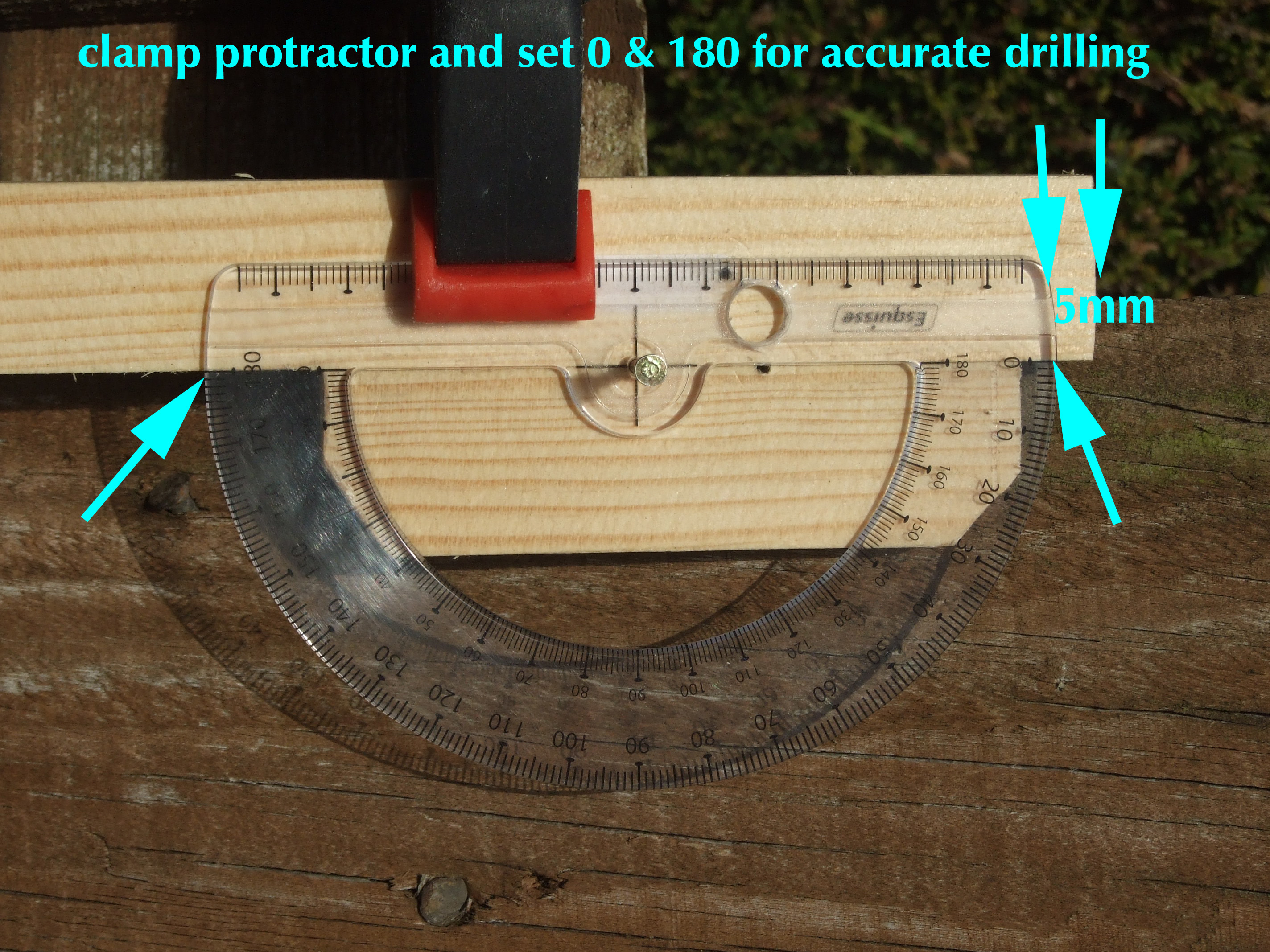
than the protractor length and screw to the larger section leaving 15mm between the top edge of the large
section and the top of the smaller added piece as shown in pic. Do not glue yet.
Step 2. Drill 2.5mm hole in protractor focal point of the arc, and pin to wood, for reading accuracy make sure that pin hole is symmetrical on the joining line of the two pieces of wood. Ignore 8mm hole in protractor body in this pic.
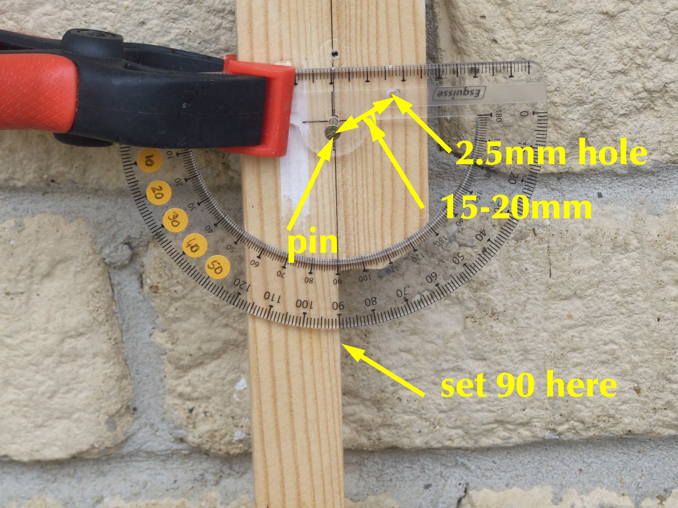
Step 3. Mark another position on the protractor body base about 15 to 20mm from the pin hole, (this measurement is dependant upon the width of wood used, rotate protractor to the 90° position and make sure that the marked hole is always on wood and will remain so when the 2.5mm hole is increased to 8 or 10mm later. Set the 90° mark as shown on the guide face which touches the dish when in the reading position. Drill 2.5mm hole. Put pencil point through this hole and mark wood for future screw position.
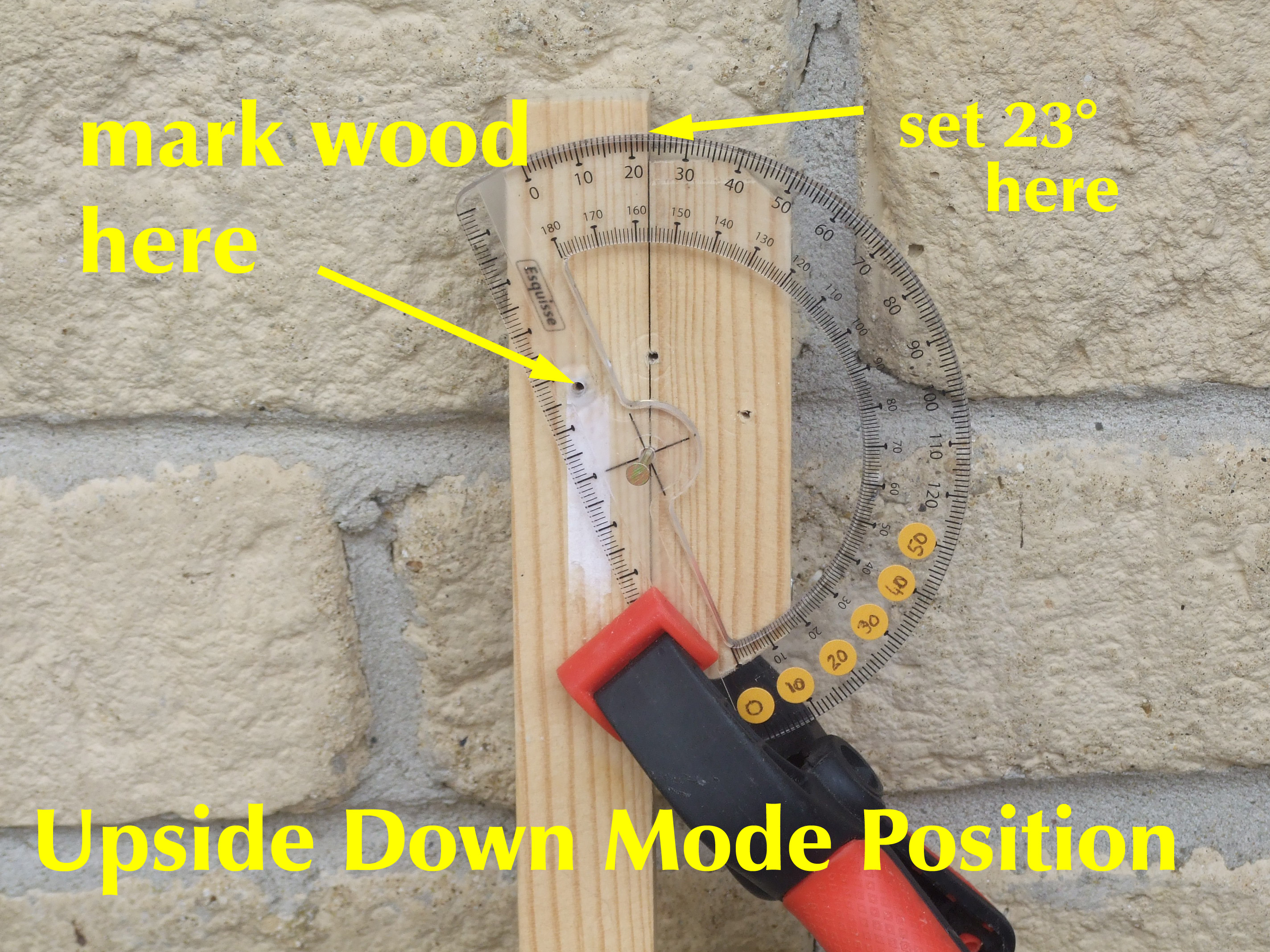
Step 4. Now set the protractor 23°,as shown in pic and clamp. Through 2.5mm hole, pencil mark wood for future screw position. 23° has been selected as midway between 18° and 28° which are the limits I have experienced with dish offset values.
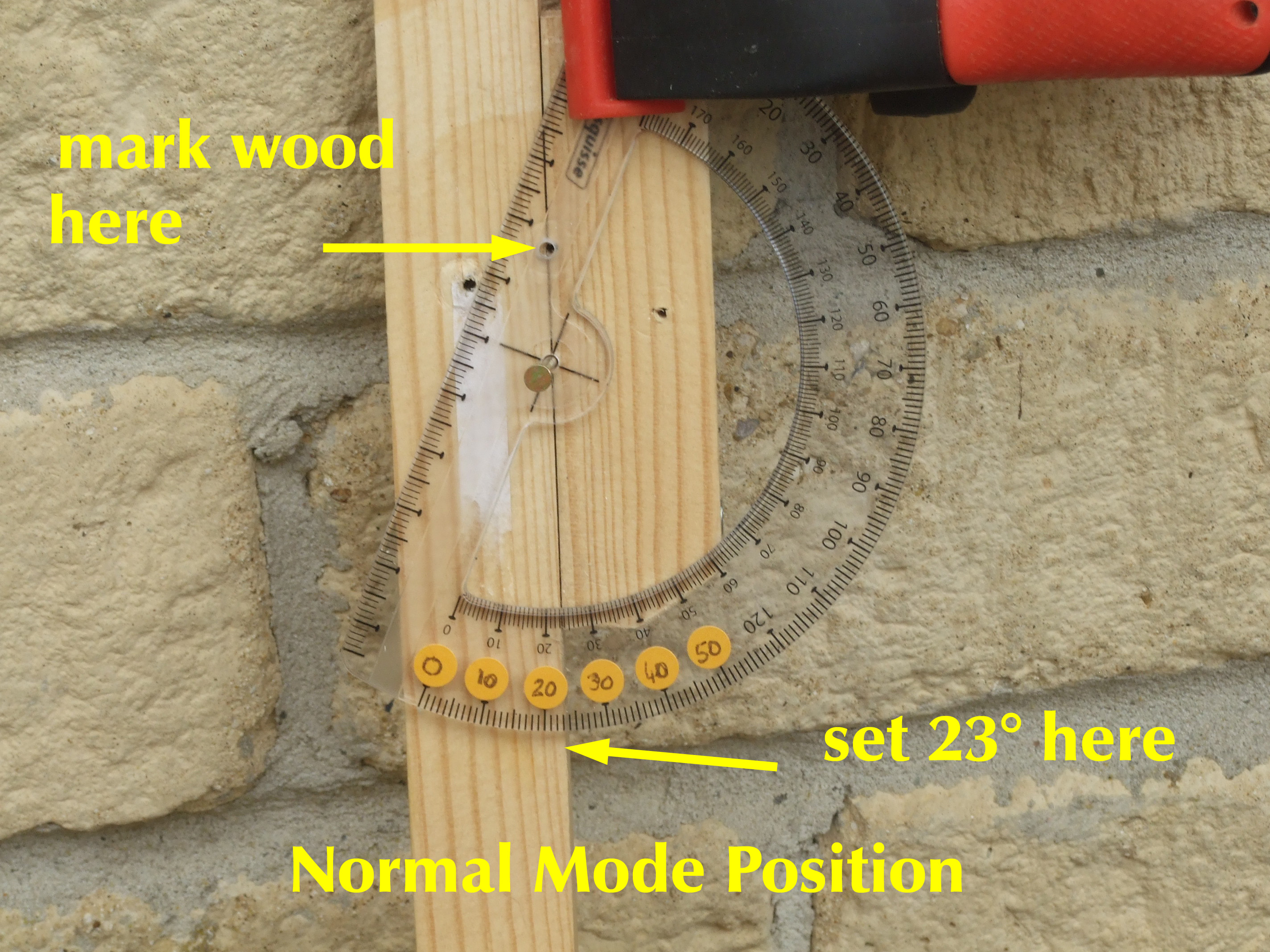 Step 5. Now place coloured spots on the 180°,170°,160°,150°,140°,130° marks and ink in 0
to 50 lettering as shown. Set 23° as shown, clamp, and pencil in this 3rd mark on wood, again for future
screw position.
Step 5. Now place coloured spots on the 180°,170°,160°,150°,140°,130° marks and ink in 0
to 50 lettering as shown. Set 23° as shown, clamp, and pencil in this 3rd mark on wood, again for future
screw position.
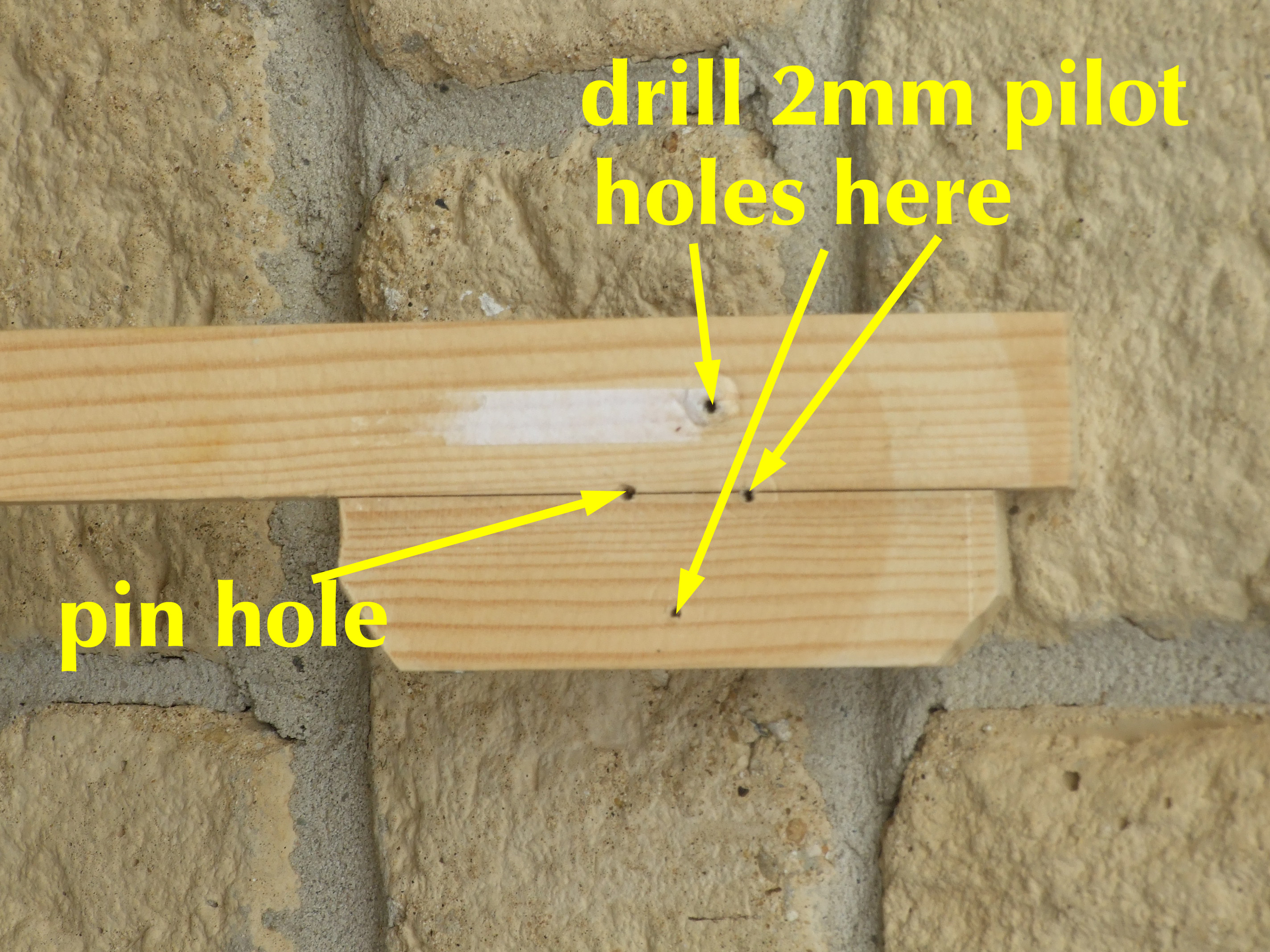
Step 6. Drill 2mm pilot holes for future 3.5mm x 16mm screw ( 6 x 1/2")
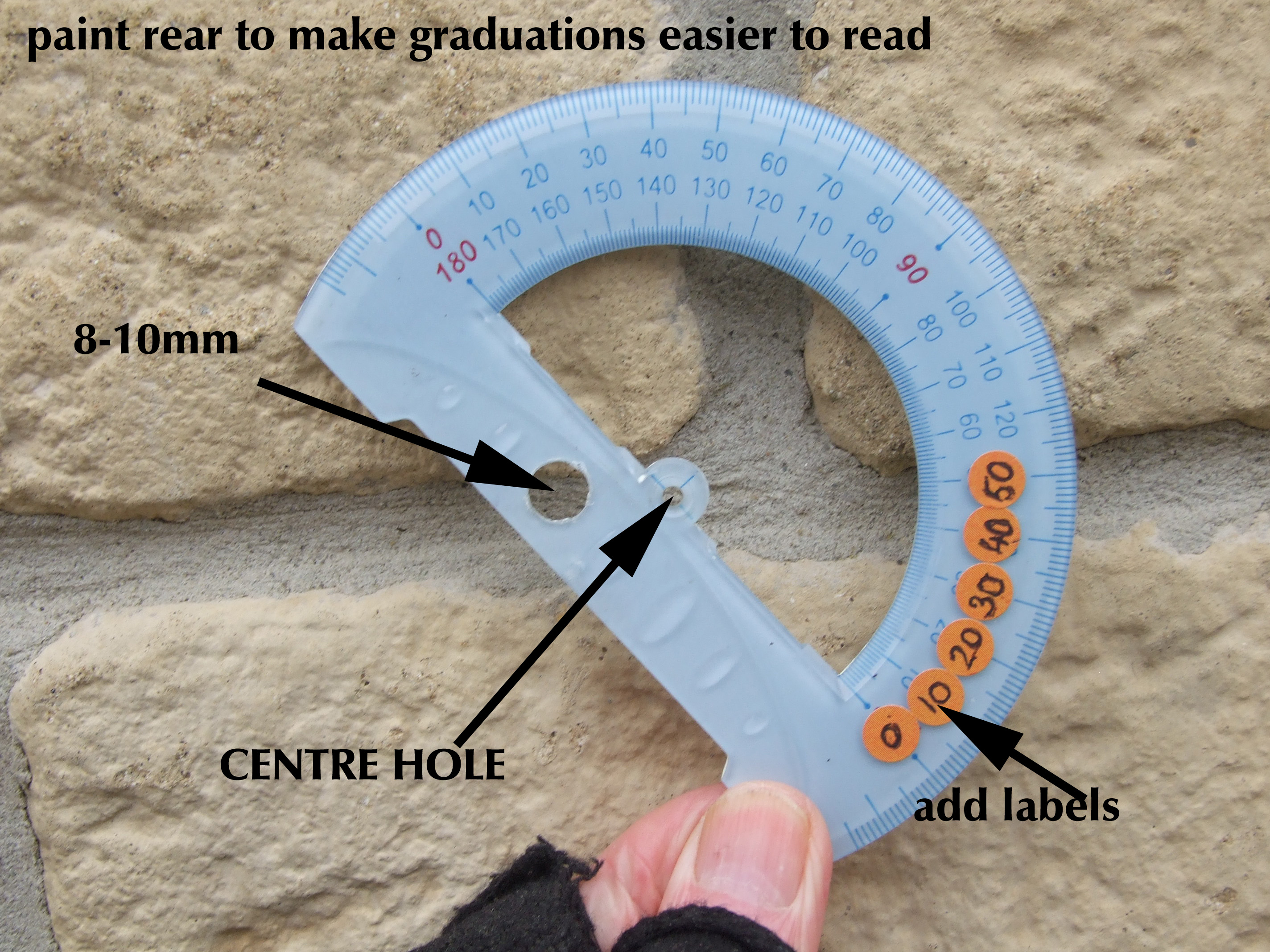
Step 7. Drill out the 2mm wood marking hole to 8mm - 10mm so that offset range can be adjusted to 18° - 28°.
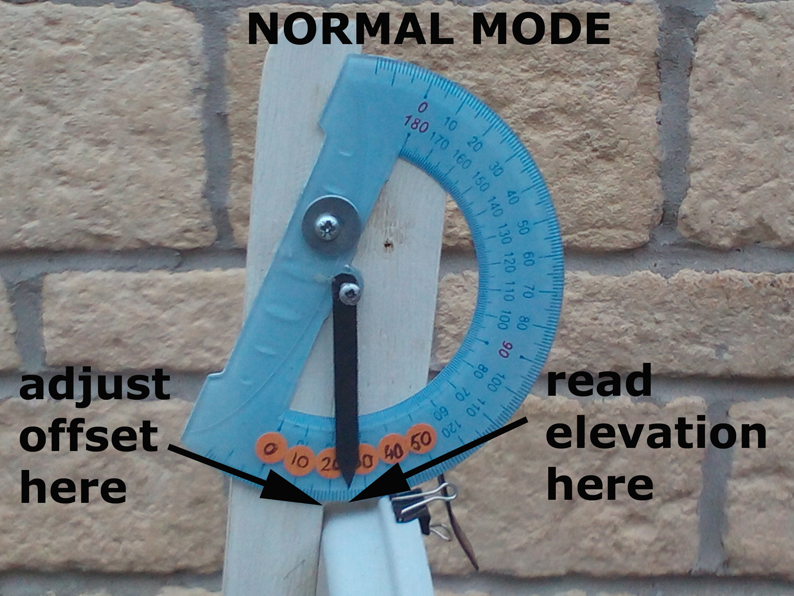
Paint the rear of the protractor with a light coloured shade so that degree markings are more clealy
visible. Add small numbered labels to make elevation angle readings easier to determine.
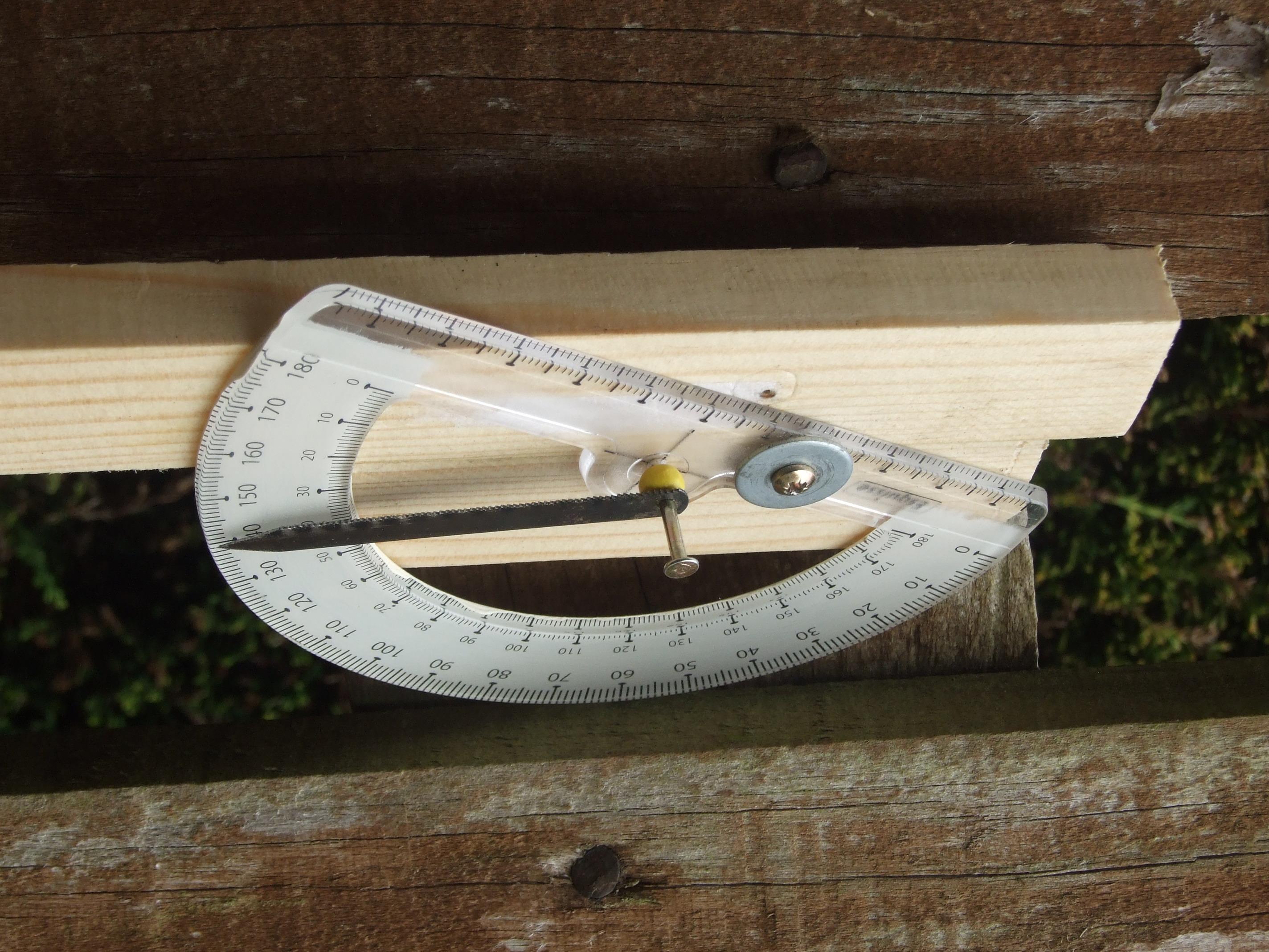
Step 8. Finally, remove locating pin from one end of junior hacksaw blade, drill out blade hole to 2.5mm, cut to length and shape pointer end with file, tin snips or gilbows, mount with wooden bead as shown on pic. Secure protractor to wood using screw and washer in the position you wish to use,
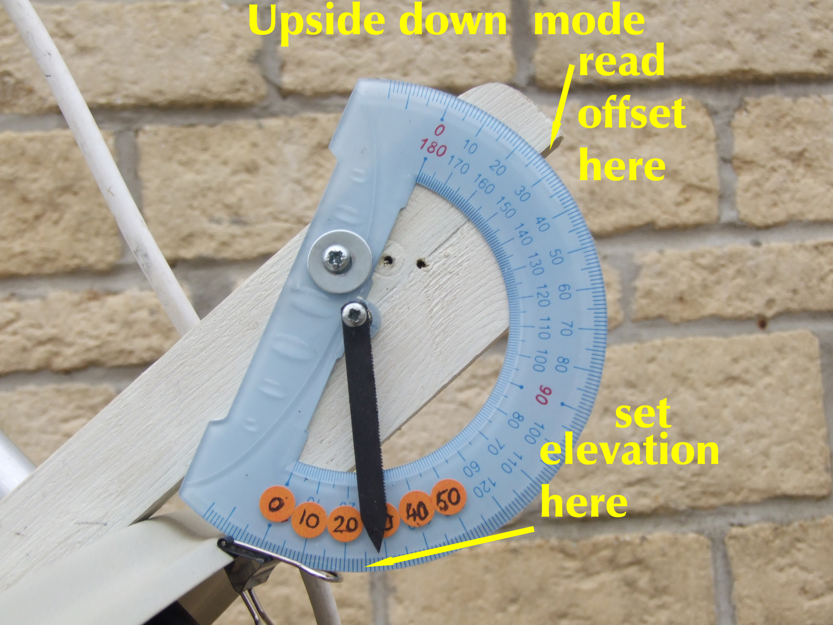
adjusted to the required dish offset value in either Normal mode or Uside Down mode. Job done.
Before starting to make the frame we have to establish the offset angle of the dish we are going to use,
as the frame dimensions are dependant upon this value. Setup the dish in either upside down or normal mode and by any means obtain a channel lock and
picture from any satellite your receiver can select, if you select a satellite other than Astra 2E or 2F make sure
you can identify the satellite from the TV picture,
Lyngsat could help with this task,
Establish from
Dishpointer,
the correct
elevation angle for your chosen satellite giving this picture. Fine tune the dish using a meter to obtain the
highest signal level and then place the elevation guide set for the correct mode, normal or upside down, on the
dish face and adjust the protractor so that the pointer reads the correct elevation figure. Tighten the screw
holding the Protractor and note the dish offset angle.
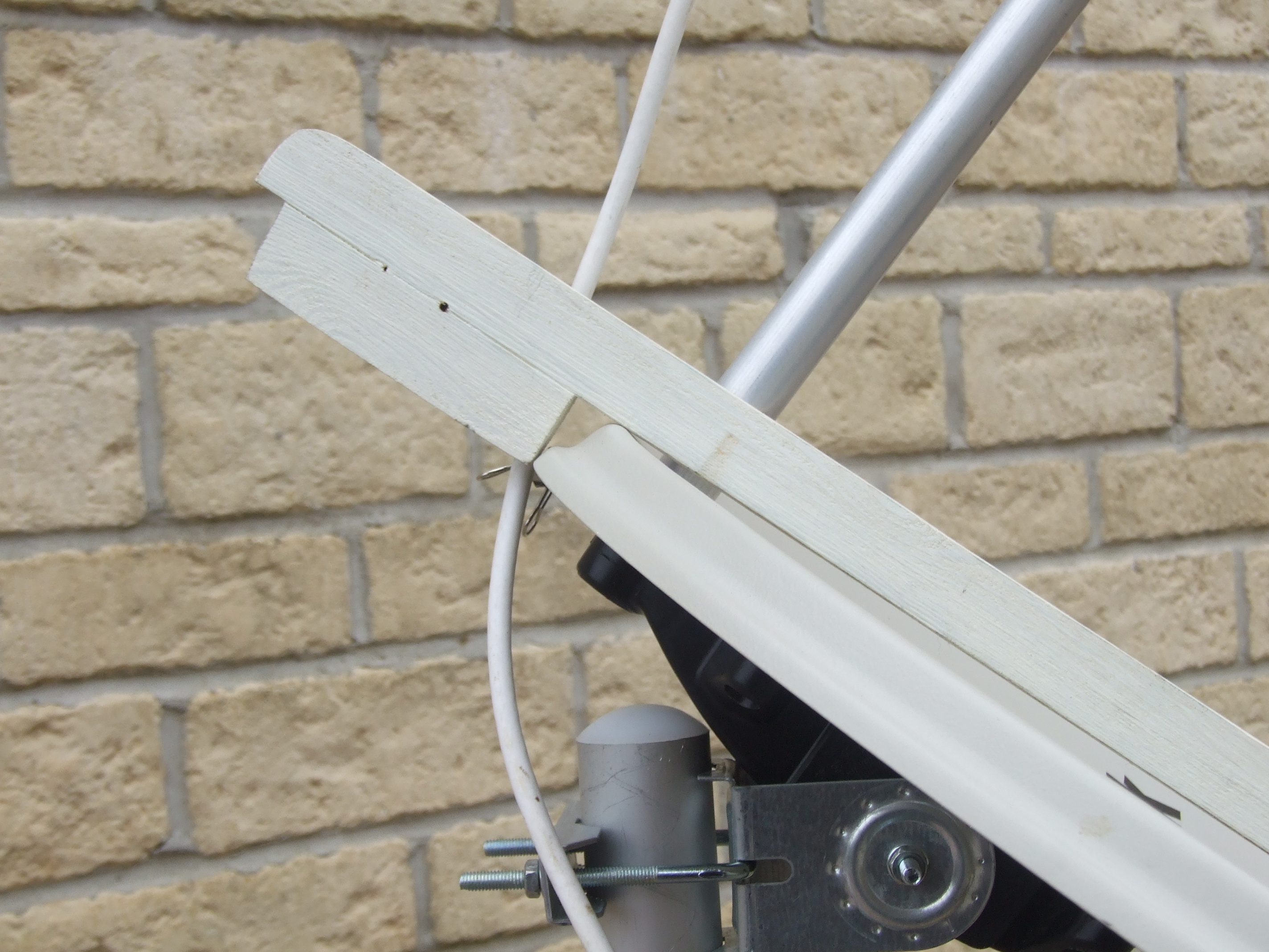
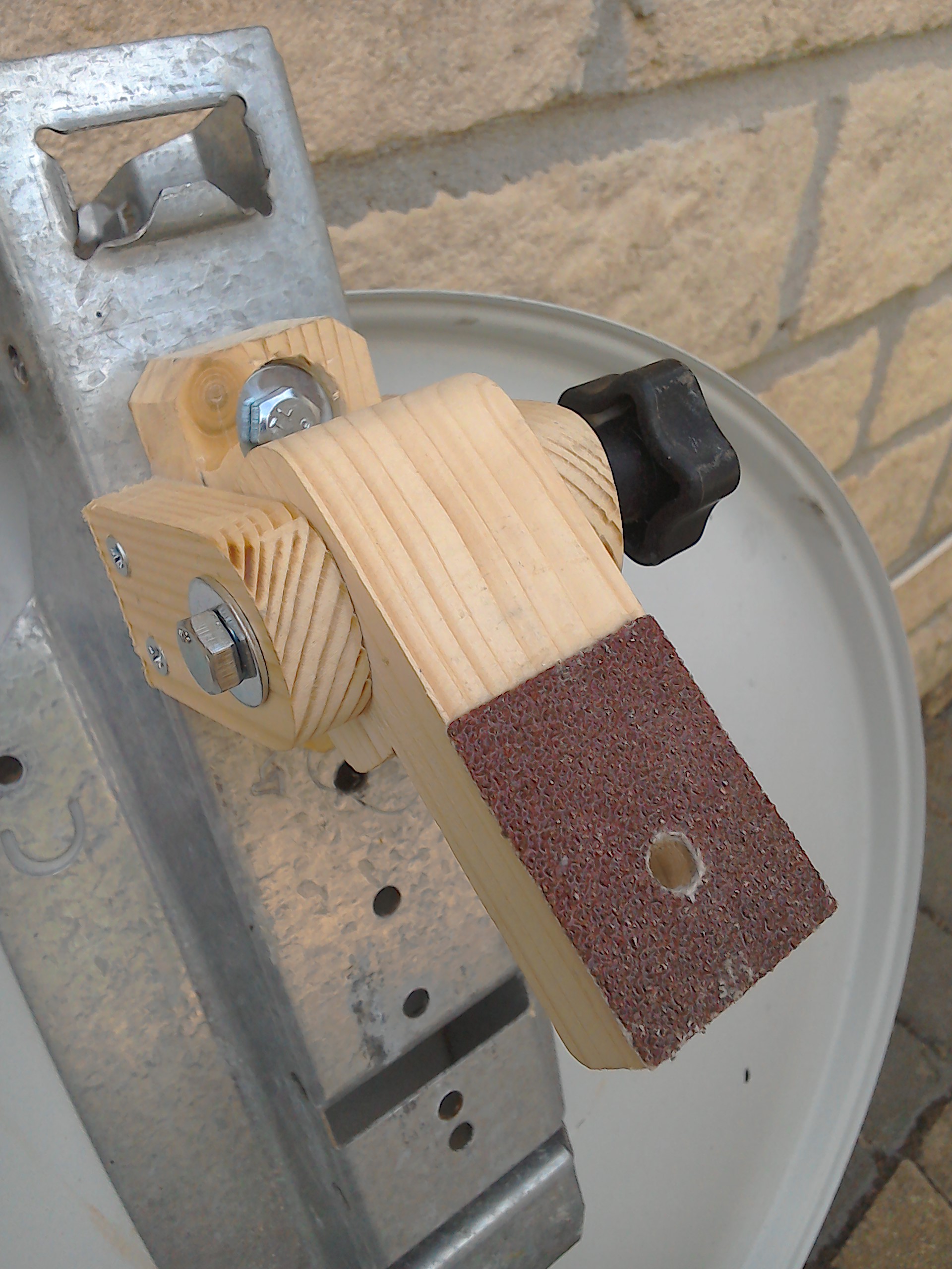
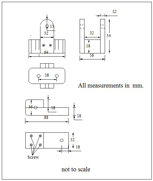
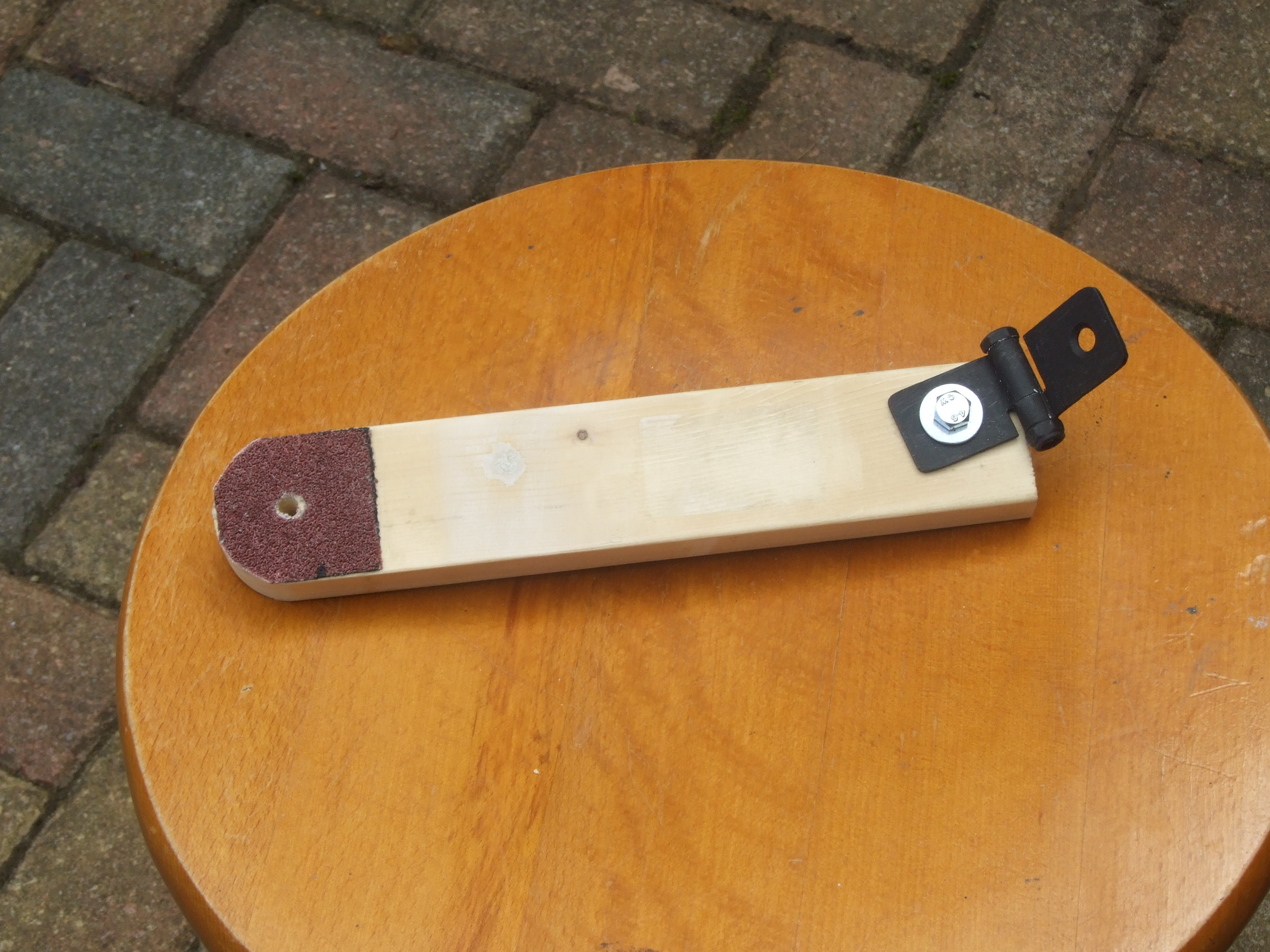
Step 1. Now that the offset angle has been found the next step is to make this hinge using the drawing below
for dimensions (all in millimetres). The red patch on the moving arm is part of a 40 grit sanding belt and is
used as a frictional pad for dish rigidity particularly in high winds. Hardware is all M6 size (drill 6.5mm holes
in wood for M6 bolts). I have no connection with any company whatsoever, and just buy from the cheapest source,
I get planed wood from
B & Q and
Wickes, hardware from
Screwfix and Control Knobs from
Radio Supplies.
These are the dimensions that I have used but modify them if you wish to suit wood that is available to you.
If you are using M6 bolts then drill all holes in wood with a 6.5mm drill bit, dampness from being out in all weathers
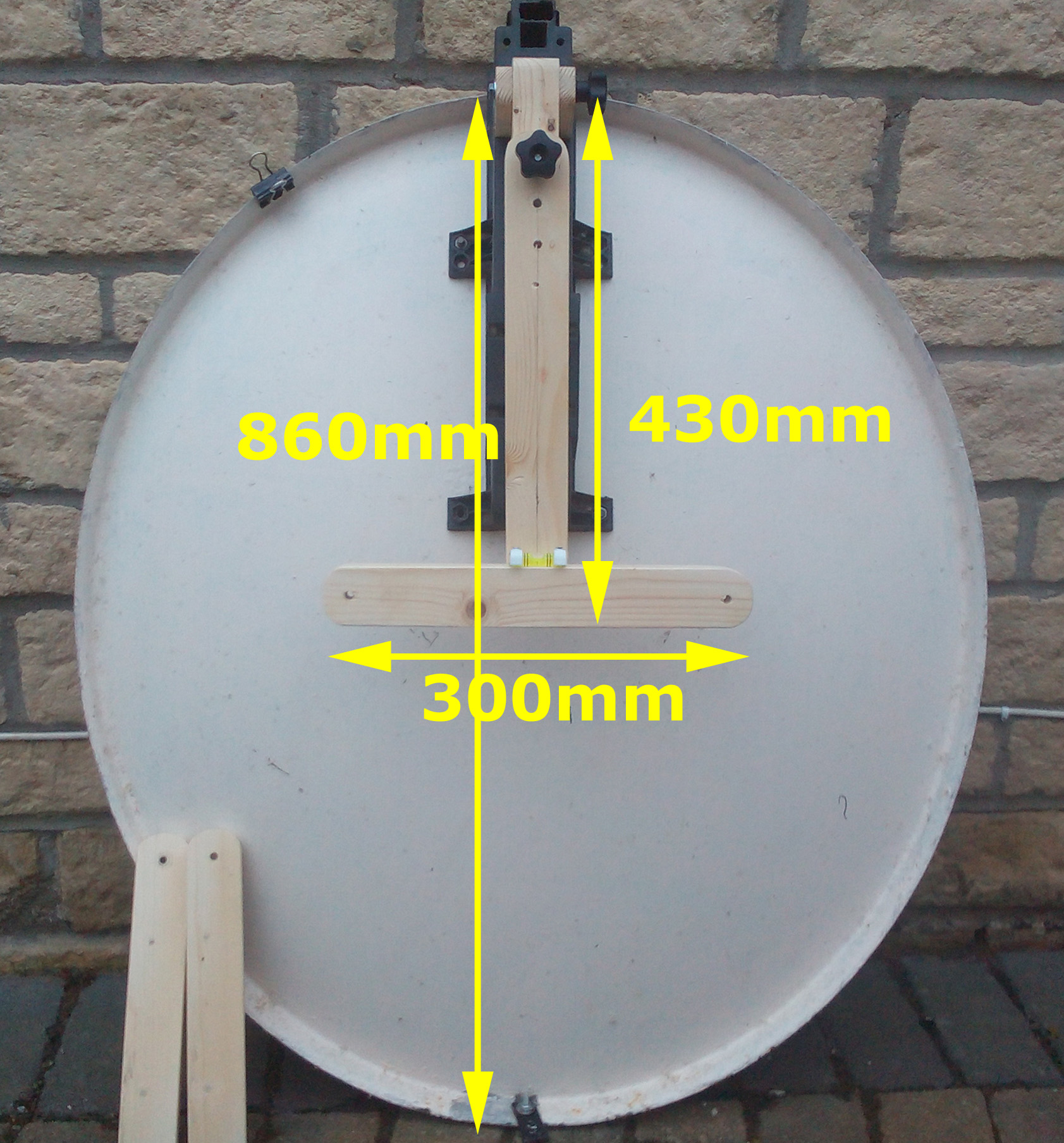
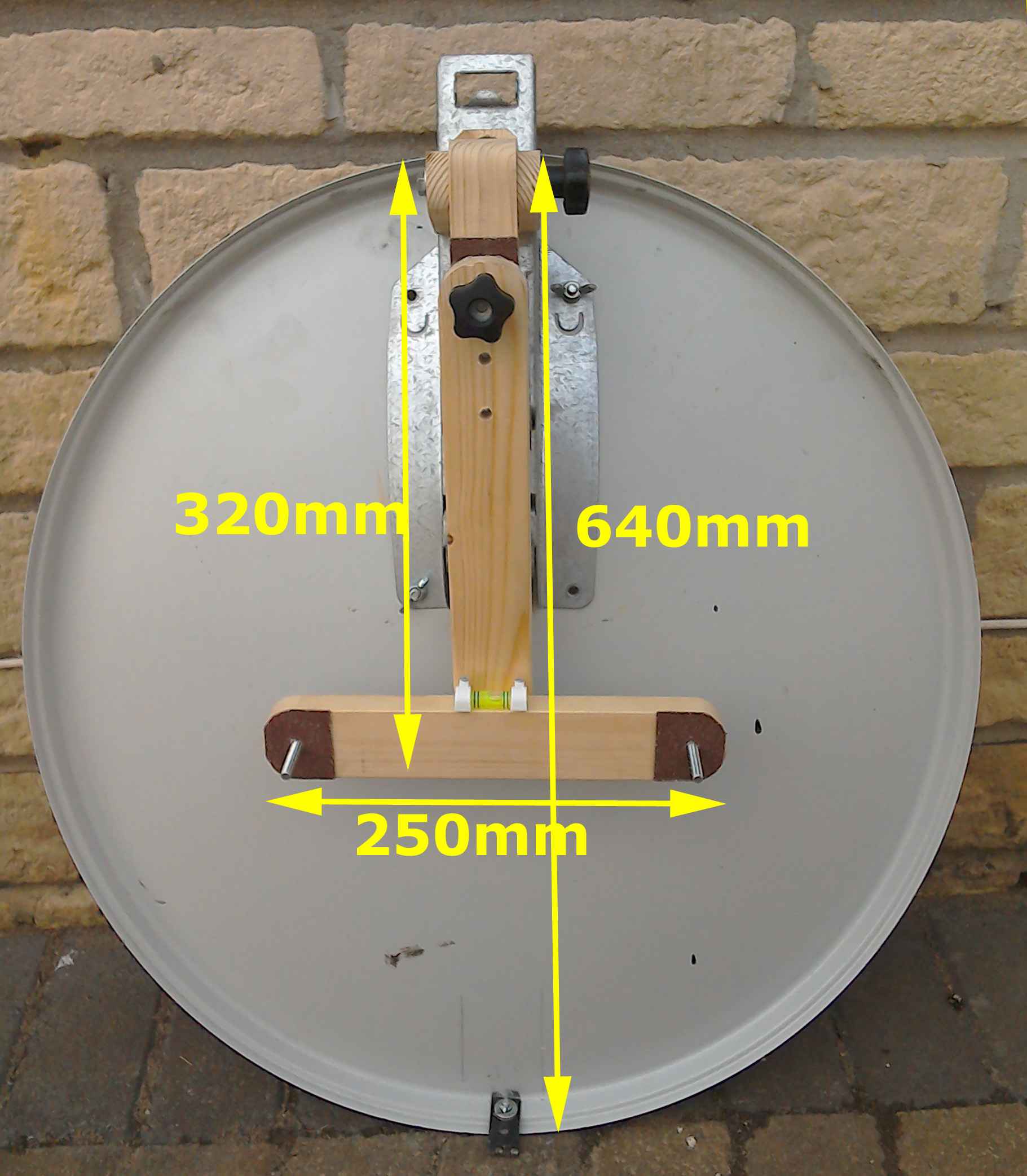
swells the wood and removing the bolts can be tedious. Make an upside down 'T' section to about these dimensions with the bottom of the horizontal arm approximately
half way along the dish major axis. The length of the vertical element of the 'T' section will depend on the
mounjting position of the hinge unit on the dish dish body, therefore the easiest solution is to state the
approximate final position of the horizontal arm relative to the dish size. When made, glue 40 grit friction pads
at each of the three ends and drill 6.5 mm holes. Next mount the spirit level bubble,
this came from
Amazon,
and is part of an orange 2 way Caravan leveling device. Push out the glass bubble
and mount with 9mm cable clips. To avoid hitting the glass bubble with a hammer when driving the cable clip nails ,
I suggest drilling out the clip holes with a 3.5mm drills and using 4 X 5/8" screws to secure.
x the angle of the dish face relative to horizontal ground
= 90 - (dish offset + required elevation)
or you can cheat and use scrap wood on a trial and error basis.
When you are satisfied with the legs, glue friction pads to their joining ends which are also drilled.
The ground securing hinges have been cut from a 100mm door hinge which has been divided into 4 equal pieces of
about 25mm each. The 2 sections have been bolted together with an M6 30mm bolt and nylon insert locking nut.
This tensions the hinge opening.
Currently in preparation.
<
 Finally, leg sizes have to be
obtained, first decide where you are going to use the dish, and the elevations required for the geographical
places to be visited. For the UK mainland 19° to 26° would be required, to include Scottish Islands lower
figure should be reduced to 16°, for France the range should be 25° to 34° and so on. This info
can be obtained from www.dshpointer.com. Using the elevation guide set to the minimum elevation angle of the
place setting will give you the final height and the leg set at 135° relative to the horizontal
can be calculated, added vertical height due to leg = (0.7 X leg length), you can also calculate this from the formula :-
Finally, leg sizes have to be
obtained, first decide where you are going to use the dish, and the elevations required for the geographical
places to be visited. For the UK mainland 19° to 26° would be required, to include Scottish Islands lower
figure should be reduced to 16°, for France the range should be 25° to 34° and so on. This info
can be obtained from www.dshpointer.com. Using the elevation guide set to the minimum elevation angle of the
place setting will give you the final height and the leg set at 135° relative to the horizontal
can be calculated, added vertical height due to leg = (0.7 X leg length), you can also calculate this from the formula :-
.
FRAME for an 80cm dish