Still under Construction
SATELLITE LOCATION
A further section has now been added for users of the popular Comag Portable Camping system using the Free To Air SL 65/12 receiver.
Before we get involved in the setting up procedure first let us consider a few technical points about the system we are trying to locate. There are 4 main satellites in the "Sky" system, 3 belong in the Astra group 2A, 2B and 2D and the fourth is Eurobird 1 owned and operated by a different organisation. Each satellite roams freely in about a 100 km box spaced about 100 kms apart except Eutobird 1 which is 200 Kms (0.3 degrees) away. To complicate matters still further each satellite has a different footprint (this is the area on the earth that the signal is directed towards) as shown in the folloing www.lyngsat.com images. Normally if you are setting up your system in the UK this information is not required as all of mainland UK is in a strong signal area, but once you cross the channel then problems start to arise the further south and east you travel in France. The Astra 2D footprint shows very strong signals (the red area) in the UK and Northern France and very weak signals (the blue area) in Northern Spain. So if you are in Northern Spain and wish to view programmes transmitted by 2D (BBC and ITV channels) then you would use one of its transponder frequencies for the setting up process. How do you know which TV programmes are transmitted by each satellite and the frequencey of the transponder, this can be obtained from www.lyngsat.com, select Europe, then the satellite (in this case 28.2°E) and download the programme list. If you still fail to obtain a picture then you have to go to 2A/B South beam which has strong signals in Spain. The Sky Digibox always sets up on 11.773GHzV which is on 2A North Beam.
...................................Astra2D.................................................Astra2A/2B North Beam ..................................... Astra 2A/2B South Beam
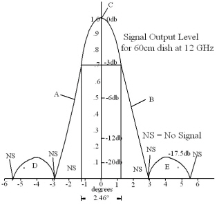 This graph is useful for those of us who use a sat meter. It shows that if the dish alignment is more than 3° from the true alignment then no signal will be received by the meter in both the azimuth and elevation settings. In real life the centre section is a cone which cannot be truely displayed in a 2D drawing. In low signal areas point 'C' on the graph is what you should aim for. To test for this point for azimuth alignment , stand behind the dish and gently pull towards you first the 3 o'clock position on the dish and then the 9 o'clock position, if you are at point 'C' the meter reading should reduce as you distort the dish face with each gentle pull. To check for the elevation alignment pull the 12 o'clock and 6 o'clock dish positions, again both readings should reduce. If any of the four readings increase then you are at point 'A' or 'B'.
Now if you are using a Sky Digibox in a weak signal area the graph also shows that setting up your system on the Programme Guide frequency of 11.778 V (2A North Beam) means you cannot obtain a peak signal on the other satellites (2B, 2D, Eutelsat) due to their physical 100km separation in the sky, so if you want to watch BBC/ITV programmes then a Manual Setup is essential and is explained later in this section. This is not a problem for users of Free to Air receivers as they can easily align their systems on any frequency.
This graph is useful for those of us who use a sat meter. It shows that if the dish alignment is more than 3° from the true alignment then no signal will be received by the meter in both the azimuth and elevation settings. In real life the centre section is a cone which cannot be truely displayed in a 2D drawing. In low signal areas point 'C' on the graph is what you should aim for. To test for this point for azimuth alignment , stand behind the dish and gently pull towards you first the 3 o'clock position on the dish and then the 9 o'clock position, if you are at point 'C' the meter reading should reduce as you distort the dish face with each gentle pull. To check for the elevation alignment pull the 12 o'clock and 6 o'clock dish positions, again both readings should reduce. If any of the four readings increase then you are at point 'A' or 'B'.
Now if you are using a Sky Digibox in a weak signal area the graph also shows that setting up your system on the Programme Guide frequency of 11.778 V (2A North Beam) means you cannot obtain a peak signal on the other satellites (2B, 2D, Eutelsat) due to their physical 100km separation in the sky, so if you want to watch BBC/ITV programmes then a Manual Setup is essential and is explained later in this section. This is not a problem for users of Free to Air receivers as they can easily align their systems on any frequency.
Now for the setup procedure. Let us assume that you are going away for the weekend to the Caravan Club site at Tewkesbury in Gloucestershire and that you have already gone through the 1st Time Setup procedure at home to establish your dish offset angle, compass error and have marked the offset degrees on the LNB if not originally marked by the manufacturer. From the chart, the nearest listed site to Tewkesbury is Gloucester, and the setup details for watching SkyDigital at 28.2° East are as follows :-
Magnetic Compass Bearing 146.3° Elevation Angle 24.2° LNB Offset -14.3°
If you do not have a chart with this data, azimuth, elevation and offset details can now be obtained from a recently opened website at www.dishpointer.com which you can visit by Clicking Here, be prepared to input an address, post code or the Latitude & Longitude co-ordinates of the site you wish to visit. If you have Microsoft Autoroute, then the co-ordinates of anywhere in Europe can be obtained using the Location Sensor found in the Tools Menu. Failing this then turn to your old school atlas. The advantage of using this site over www.ses-astra.lu is the azimuth figures are given in Magnetic Degrees as opposed to True Degrees on the Astra website (which are meaningless for most of us).
Before starting the journey, place the chart, compass and triangles in a handy position in the car. On arrival, take a rough compass bearing of 146° and note its position relative to the camp office. As you drive around the site with this bearing in mind you should be able to avoid pitches which are close to tall trees that could obstruct the satellite signal.
Location, location, location.
- Having sited the van, the task of location can now
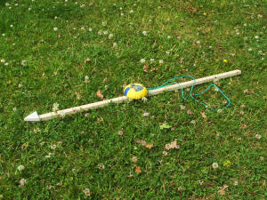 begin. Place the wooden pointer on the ground with the arrow head roughly South East. Mount and align the compass centrally along the pointer length towards the arrow head. Rotate the pointer (with the mounted compass) until the magnetic reading is the nearest that the compass scale will indicate to 146.3°, which will be 146°. Remember, the greater the accuracy of setting the pointer the easier the setup will be.
- Remove the compass without altering the pointer position and take another bearing looking along the length of the pointer with the compass held at waist or eye level, ( keep compass away from metal belt buckles and metal watch straps ). If this second reading is still 146° then the pointer is correctly aligned and the first reading has not been distorted by iron or steel objects buried in the ground under the pointer. If the readings are different, then the pointer has to be realigned to the second reading.
If there is a possibility of trees obstructing the signal, check this by standing behing the
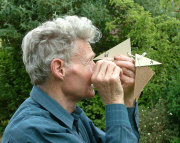 pointer looking along its length towards the arrow head, select the triangle whose angle is just less than the required elevation of 24.2°,(i.e. the 22.5° triangle), and hold it to the eye with the base side horizontal, look along the hypotenuse. If you see clear sky you will have a signal, if you see trees in your line of sight, move to a new position and repeat all the above steps again, (if you can see clear sky between trees, this is OK provided the gap will not become too small when the wind blows and the tree trunks and branches move in the wind, if the gap is greater than 6 times the width of your dish everything should be fine ).
When you are happy with your selected position,
 mount dish centrally over pointer with LNB facing the arrow head. Mount the elevation guide onto the LNB arm or on the face of the dish and adjust the dish rear pioving arm until the angle finder reads 24.2° signal degrees. If the ground is very uneven or sloping, adjust one of the rotateable rear legs until the crossbar is roughly horizontal. Tighten the thumbscrew to lock pivoting arm and thus the elevation angle, or however you adjust azimuth and elevation on your system.
Finally, rotate the LNB to -15°. This is a very important adjustment as it increases the
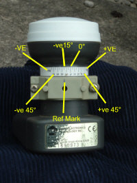 signal quality level in digital transmissions and is a must when using a small 39 - 45cm dish in wet weather for Astra 2D in low signal areas in Europe ie South of La Rochelle in France.
Connect the cable from the LNB to the sat meter 'LNB' connector, and the digibox
 receiver cable to 'RECEIVER' connector.
If you are using a Free to Air receiver such as the very popular Portable Satellite Camping System made by Comag and sold by Maplins, Aldi, Maxview etc with the SL 65/12 receiver then Click Here, to bypass the Sky Digibox setup details.
Sky Digibox Location
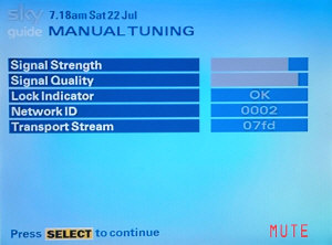
Switch on power to digibox and television and with the Sky remote control select 'Services' - '4' -
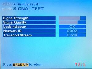 '6' to obtain the Signal Test screen showing the Signal Strength and Signal Quality bars, check to see if Lock Indicator is set at OK and Network ID is 0002. If your pointer was correctly set, these indications will often appear immediately after switching on. Rotate the small gain knob clockwise until the sat meter reading is in the middle of the scale range. (About 5 if the maximum is 10 as in the above photo, note the position of the control knob by its white line). Standing behind the dish very gently place your finger at the 3 or 9 o'clock position on the dish face and push or pull the face slightly whilst watching the meter needle.The needle will change position whilst distorting the dish face. Note whether pulling or pushing increases the meter reading. Now adjust dish azimuth by picking up rear legs until they are just clear of the ground and rotating them to the right and then left a millimetre at a time until a maximum reading (about 9 or 10) is obtained on the meter, reduce reading to mid range again and continue further dish adjustment until reading approaches 9 or 10, keep reducing needle to mid range until no further increase in meter reading is experienced, the azimuth adjustment is now finished. We must now obtain the best elevation setting, set the meter to mid range (about 5), adjust the rear legs forwards or backwards only until maximum meter reading obtain, reset meter to 5 and continue adjusting elevation angle until no further increase obtained. If your system has a true vertical adjustment to correct for sloping ground then adjust to obtain a further maximum reading on the sat meter. Finally, tighten thumbscrews or tripod ubolt clamps, fit ground pegs to secure against winds.
 If you are using an SLx sat meter then sometimes when receiving a strong signal it is impossible using the control knob
 to reduce the meter reading of 10 to about 5. As you will see in the photograph the control knob is fully anticlockwise although the meter needle is 10+ The meter manufacturers state in their IMPORTANT NOTES :-
"If your LNB has a gain higher than 60db, insert a 5db satellite attenuator between the LNB and the SLx Satellite Finder."
The only problem is, all dealers sell the SLx meter but none realise there is a need to sell the attenuator as well.
<The solution is to place a damp leather across the face of the dish to reduce the signal strenth,
 then you can continue to adjust the dish for the best signal in the normal way. Do not forget to remove the leather when dish fully aligned.
When you have achieved the best signal level remove the meter (and leather) and connect the two cables
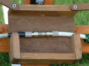 together with a double female 'F' connector.
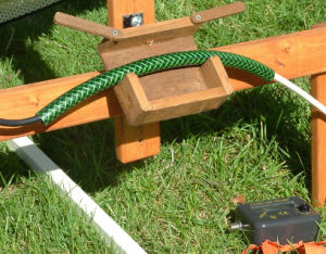
Keep the connection waterproof by covering with a piece of garden hosepipe. Task completed
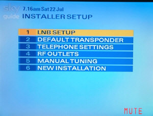
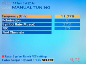
If after completing the above setup, when you try to obtain a BBC or ITV programme via the programme guide and receive the message "No satellite signal being received" then you could try to do a Manual Setup, this happens when you are in a weak signal area on the continent. To do this press the SERVICES button on the remote controller followed by 0, then 1 and finally SELECT to select the Installer Setup Now select item 5, MANUAL TUNING
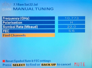
When the MANUAL TUNING screen appears, alter the frequency to 10.773 Polarisation H, Symbol Rate 22000, FEC 5/6. This is the BBC transponder for BBC1, 2, 3, 4, News 24 .
Finally select FIND CHANNELS and press Select.
Now readjust dish position to obtain highest readings on the Signal Strength and Signal Quality bars. Finally return to Programme Guide and select BBC1 which should provide a picture..
Comag Location
Switch on the mains to the Television and the SL 65/12 FTA receiver, which will give you either a
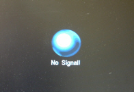 picture or the following screen. Either way, for the sake of a few extra minutes of adjustment do continue with the full set up procedure to obtain the best possible picture, if you don't and you experience a heavy downpour or thunderstorm your picture might freeze.
Press the "MENU" button on the receiver remote control to enter one
 of 4 possible screens
 1. Channel (screen symbol: TV set)
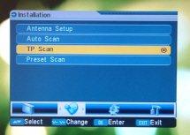
2. Installation (screen symbol: satellite dish)
3. System Setup (screen symbol: gearwheel)
4. Setting (screen symbol : tools) screen. Use the left or right arrow keys to select the INSTALLATION screen (sat dish) as shown on the left. Use the up or down arrow keys to select "TP SCAN" facility, press the OK button to bring up the next screen.This screen enables the correct SATELLITE and Transponder (TP) frequency to be selected and
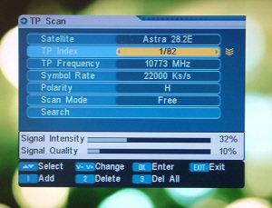 gives two bar indicators of received Signal Strength and Signal Quality. The grey bar readings of 32% and 10% indicate no signal being received and should change to blue when a signal is obtained by dish alignment. If the SATELLITE shown is not ASTRA 28.2°E then highlight the row with the up and down arrow keys, select "SATELLITE", use the left or right arrow keys to select ASTRA 28.2°E from the available list.
Now to adjust the dish.
Rotate the small gain knob clockwise until the sat meter reading is in the middle of the scale range. (About 5 if the maximum is 9 or 10). Standing behind the dish very gently place your finger at the 3 or 9 o'clock position on the dish face and push or pull the face slightly whilst watching the meter needle.The needle will change position whilst distorting the dish face. Note whether pulling or pushing increases the meter reading. Now adjust dish azimuth by picking up rear legs until they are just clear of the ground and rotating them to the right and then left a millimetre at a time until a maximum reading (about 9 or 10) is obtained on the meter, reduce reading to mid range again and continue further dish adjustment until reading approaches 9 or 10, keep reducing needle to mid range until no further increase in meter reading is experienced, the azimuth adjustment is now finished. We must now obtain the best elevation setting, set the meter to mid range (about 5), adjust the rear legs forwards or backwards only until maximum meter reading obtain, reset meter to 5 and continue adjusting elevation angle until no further increase obtained. Tighten thumbscrews or tripod ubolt clamps. The Signal and Quality bars should now appear blue as below. One of the disadvantages of using a Free to Air
Click here to visit www.Lyngsat.com for 28.2°E.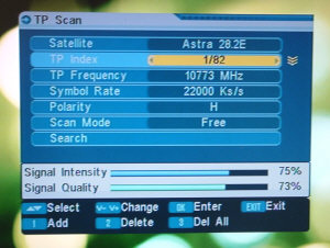 receiver is that the programme content has to be continually checked for new channels. You can do this first of all by visiting www.lyngsat.com which has the up-to-date channel and transponder lists, these can be downloaded and viewed at leisure or printed directly from the website. If additions have to be made, then this is the screen you would select to add and search new transponders and search existing transponders for newly added channels.
When you have obtained the best possible signal strenth and quality figures
 press the exit button twice to obtain the channel picture.