Vertical Transponders
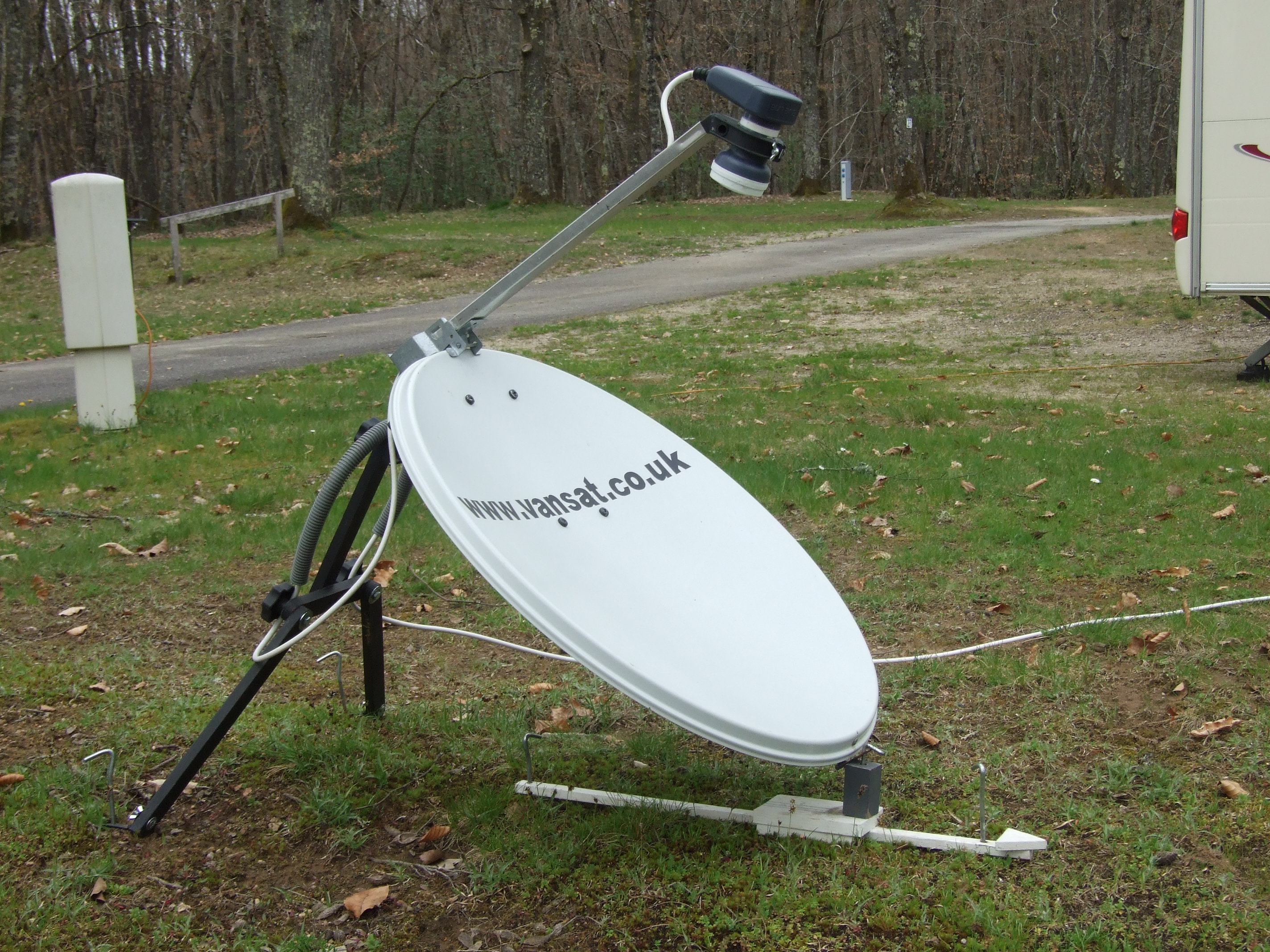
Many people have difficulty with the concept of an upside down satellite dish, when on site I am often
asked "Will it work ?", "Do you really get a picture ?" and the answer is an emphatic YES. Let me try and show how it
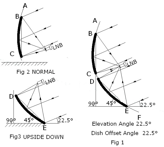
works. Left is a drawing Fig 1 of a large concentric dish AF elevated to receive a signal of 22.5 degrees.
Now the small dishes required for our use are called 'offset dishes' and are formed by taking a small
section BC from a larger dish but with the LNB set so that it does not obscure any of the incoming signals
from reaching the dish reflector, this makes it more efficient and means the reflector can be made smaller.
The section CD of the large dish does not receive any signals because they are blocked by the lnb. Now the
section DE (UPSIDE DOWN MODE) Fig 3 which is a mirror image of BC (NORMAL MODE) Fig 2 is also receiving
the same signals but the angle that the dish face makes with the ground (angle X) is entirely different,
90° in the case of BC and only 45° in DE, in addition the LNB position is altered from the
bottom of the dish major axis (Normal) to the top of the major axis (Upside Down). This difference is most
welcome especially when wind resistance is to be considered. The section BC can be anywhere along the arc AC
depending on the offset angle required by the dish manufacturer. The dish offset figure is the received
signal elevation when the dish face BC is set to true vertical,(X=90°) and about 45° (in the
UPSIDE DOWN mode) DE. In our drawing above the offset angle is 22.5°. As the section BC moves closer
towards point A, then the angle the sectional dish face BC makes with the ground (X) increases. Lets say the
sectional dish face increases by 5°,then in order to restore the sectional BC dish face to 90°
the elevation angle of the large concentric dish AF would have to be increased by 5° to 27.5°,
which would be the new offset angle. This figure will be important later on for anyone wanting to copy the
plans to make a homemade elevation guide and dish frame (for their own personal use only). It is also
helpful in everyday setups with a tripod and no aids, starting from the vertical and knowing the
elevation required tells you which way to adjust the face forward or backwards.
For those interested in theory, angle X can be calculated as follows :-
Upside Down Mode X = 90 - (dish offset angle + required elevation angle)
Normal Mode X = 90 - (required elevation angle - dish offset angle)
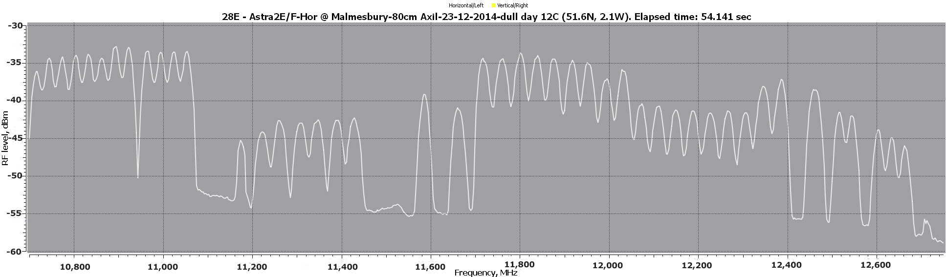
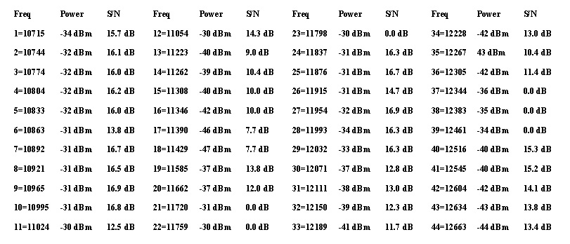
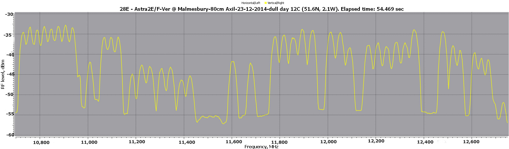
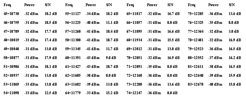
Having shown that the Upside Down dish works, the real question is, " How well does it work ?" Below are
4 charts for an 80cm dish in Malmesbury (Wilts) looking at Astra 2, 28.2° East, date Dec 2014 showing
Frequency Spectrum power output graphs, one for Horizontal transponders the lower one for Vertical transponders
together with a table of test results of signal power in dbm and signal to noise level in dbs, all together
they show the excellent performance that can be obtained with a dish in the upside down mode. I have used this
80cm as a reference in the UK because it is the dish I carry for France, then a direct comparison can be made
against the weak signals in the south of France. To obtain these figures I use an Inveto Black Ultra lnb with
an Hd S2 Q Box TBS 5922 together with CrazyScan and EBS Pro & Windows XP software programmes. Normal mode
results will be less than these not because the dish is any different but the crude ubolts and clamps make
it almost impossible to achieve maximum performance because the dish settings alter during the final tightening
of the clamp bolts and also there is no adjustment for sloping ground if a tripod is being used. This should not
be an issue in the UK where the signal is strong, but becomes a major problem when setting up outside the
footprint area on the Continent. The Internet-via-Satellite Company 'Tooway' overcome this problem with vernier
azimuth and elevation adjusters built into the dish body, but their dishes are very very expensive.
Horizontal transponders
Vertical Transponders
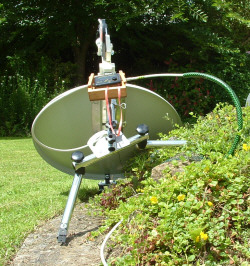
My objective in formulating the design was to get rid of the popular tripod
vertical pole together with the crude ubolts and clamp fixing, which are OK for
one off house installations but I think totally unsuitable for daily setups whilst on
the move and especially in areas outside the footprint region. The design is very simple
in concept using, a lockable hinge on an inverted 'T' elevation arm with two adjustable legs.
Very easy for a DIYer to make in a couple of hours with a material price for basic items of
about a fiver.
The reflector is secured to the ground with a ground peg via another hinge
acting as the focal point for the rotational azimuth adjustment, elevation adjustment is a
forward or backward movement of the hinged arm which has a spirit leved added for levelling,
job done.
The procedure uses an accurate computer-calculated 'look-up' table with
settings for magnetic azimuth (compass bearing), dish elevation and LNB offset.
A wooden pointer is used to retain the compass bearing instead of
trying to remember its exact direction. There are today, numerous alternatives
in place of the paper chart for Android device owners, with offline apps like
'Satellite Director' by Zekitez (although skew figures for Astra Satellites are
7.5° too high) and online web based sites like www.dishpointer.com
which can be used to display Mag Azimuth, Elevation and lnb skew having arrived
at the camping location if wifi facilities are available.
.
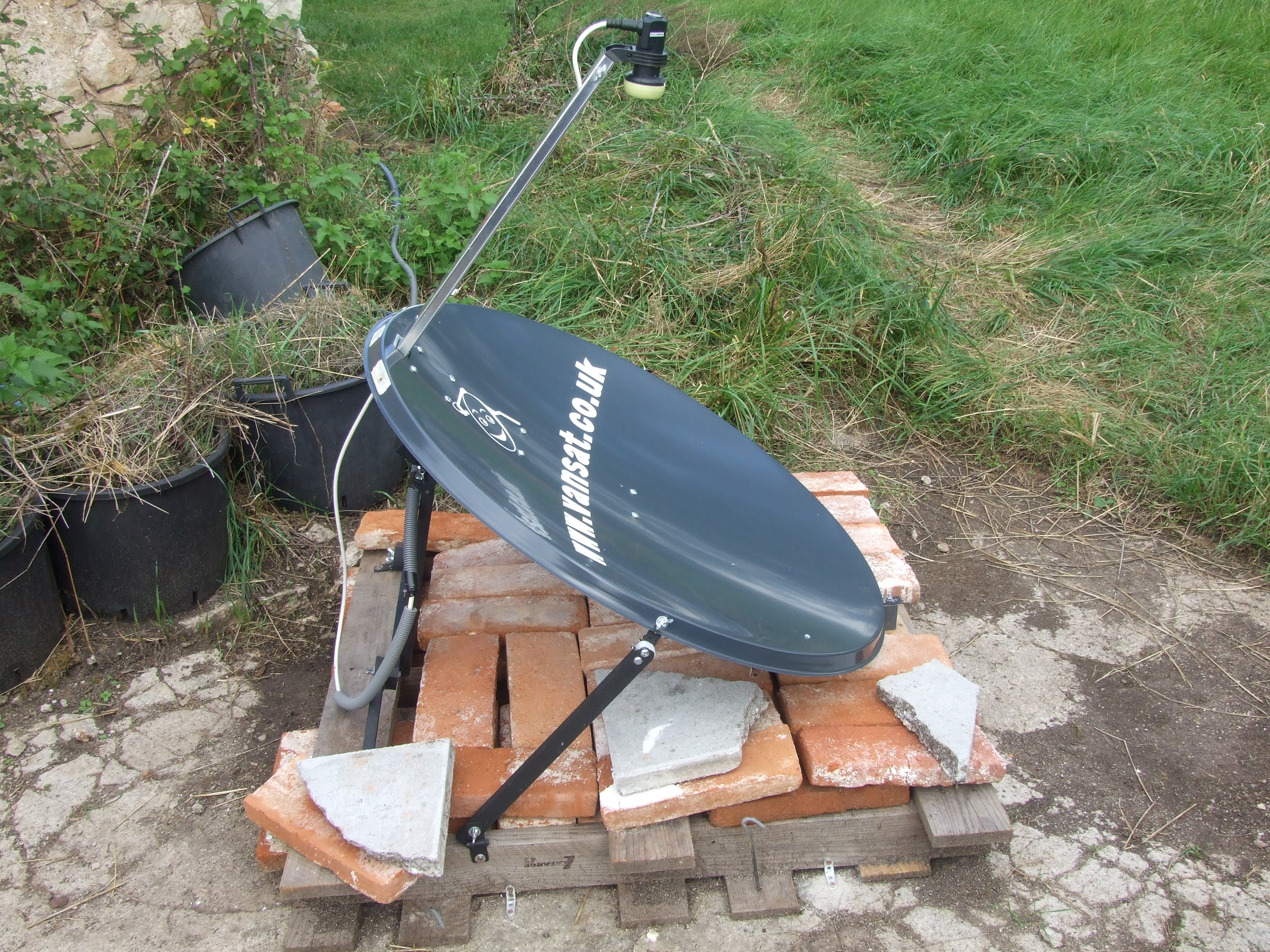
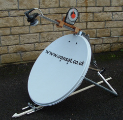
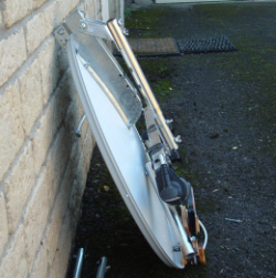
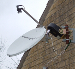
For sites outside the footprint areas where very high wind are experienced (up to 200 kph in south of France )
storm bars can be attached as shown in this pic of a 1M dish with an Inveto Black Ultra single lnb on a palet
weighed down with bricks near Albi. This arrangement was used because the property owner did not wish for a
permanent installation. Storm bars can also be used to correct flexs in larger offset reflectors (1.2M upwards)
made from thin pressings less than 0.8mm. This unit has been in service for a year and there has not been any
loss of service.
C/N test levels for 2E and 2F were minimum 10.7db on transponder 10773H, maximum 14.6db on 12581V.
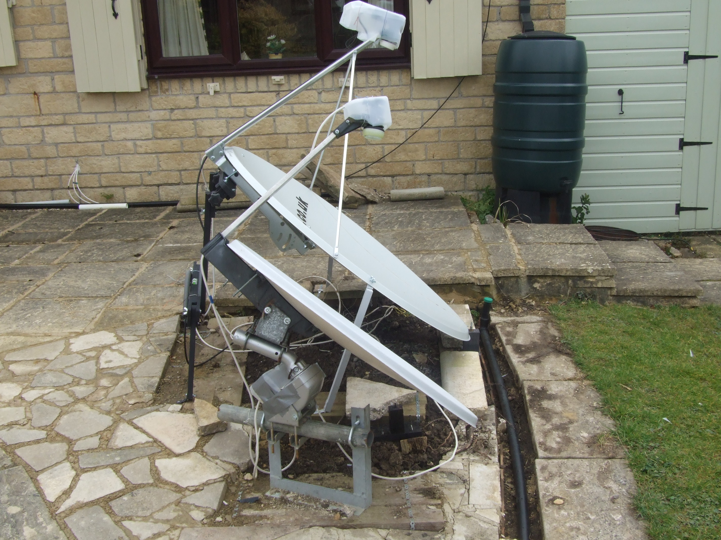 The upside down mode is also very useful for motorised systems, very easily installed, only requirement
is for a horizontal pole in the base bracket, the zero reference position setting is done in an
instant with an elevation guide which should result in good signal levels at limit settings.
To obtain this reference elevation go to any website or app like
Dishpointer,
select the
satellite at 0 East (Syracuse 3A), put in you latitude and longitude details and the elevation will be given.
If you have a computer programme for the elevation calculation you can ask for an imagiary satellite
at 0.1 degrees west. The larger dish behind the 80cm motorised unit is a 1.2M test rig looking at
Arabsat 26E to check frame rigidity and wind resistance over a long period of time as the dish
flexes easily, hence the storm bars which are just visible.
The upside down mode is also very useful for motorised systems, very easily installed, only requirement
is for a horizontal pole in the base bracket, the zero reference position setting is done in an
instant with an elevation guide which should result in good signal levels at limit settings.
To obtain this reference elevation go to any website or app like
Dishpointer,
select the
satellite at 0 East (Syracuse 3A), put in you latitude and longitude details and the elevation will be given.
If you have a computer programme for the elevation calculation you can ask for an imagiary satellite
at 0.1 degrees west. The larger dish behind the 80cm motorised unit is a 1.2M test rig looking at
Arabsat 26E to check frame rigidity and wind resistance over a long period of time as the dish
flexes easily, hence the storm bars which are just visible.
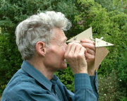
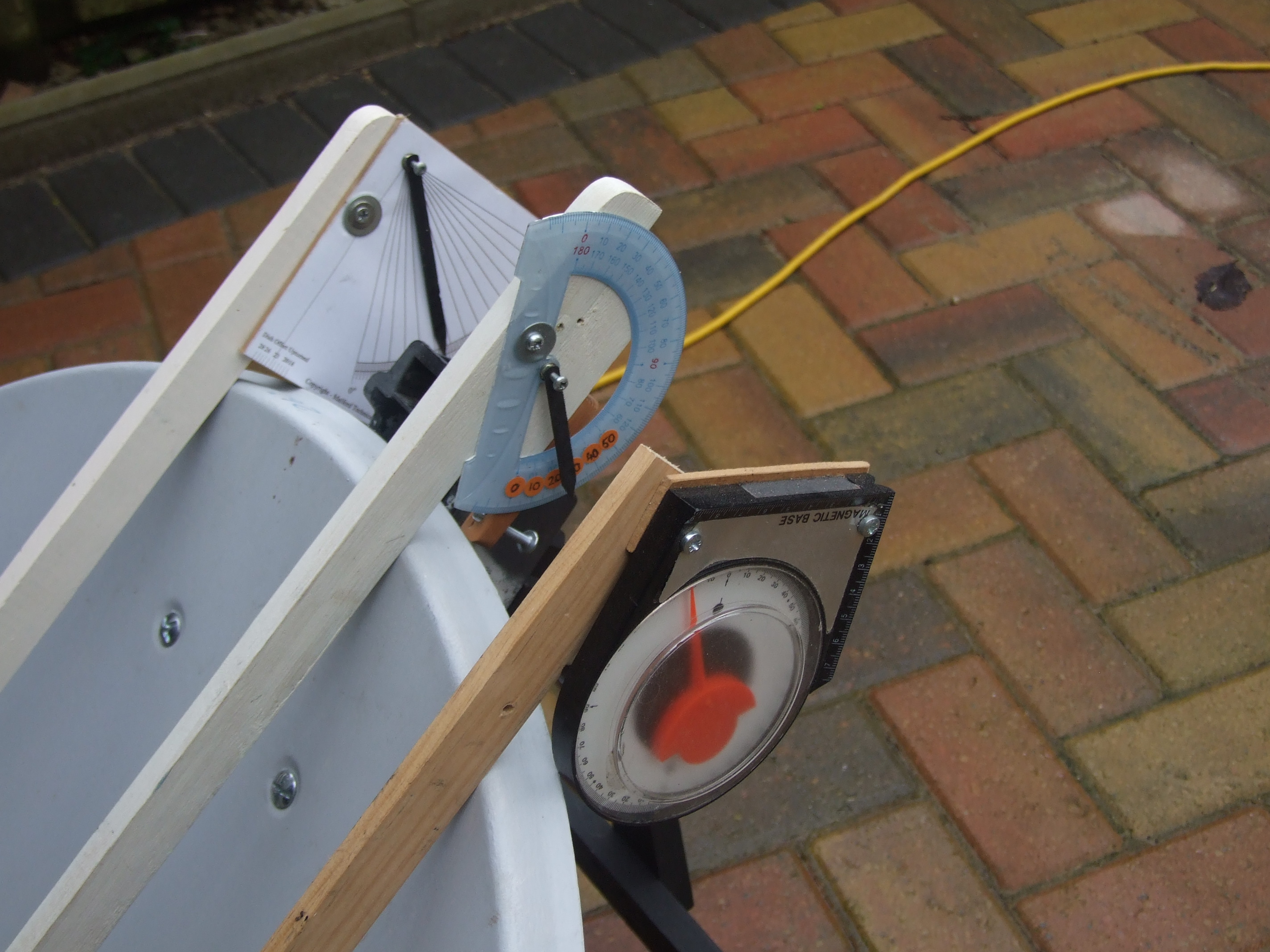 To make the elevation adjustment easier, a guide has been designed
which sits on the face of the dish, the indicating
pointer gives a direct signal elevation reading irrespective of the slope of
the terrain. The guide which sits on the dish face can be used with a slight
rotational adjustment on both UPTURNED and NORMAL mode dishes. This shows how easy it is to make
using a school protractor (the larger the better) with a junior hacksaw blade cut to size with a
pointed end as an indicator mounted at the compass focus. Full instruction are available on the
Charts and Plans Page.
To make the elevation adjustment easier, a guide has been designed
which sits on the face of the dish, the indicating
pointer gives a direct signal elevation reading irrespective of the slope of
the terrain. The guide which sits on the dish face can be used with a slight
rotational adjustment on both UPTURNED and NORMAL mode dishes. This shows how easy it is to make
using a school protractor (the larger the better) with a junior hacksaw blade cut to size with a
pointed end as an indicator mounted at the compass focus. Full instruction are available on the
Charts and Plans Page.
For normal mode setups the dial is rotated by 45° to an alternative position.
Another useful aid is a set of 11 hardboard triangles each with a base
length of about 10 cms (4") and angles of 15°, 17.5°, 20°,22.5°, 25°, 27.5°,
30°, 32.5°, 35°, 37.5° and 40° which are used to see if clearance is available
above trees in the path of the required satellite.
 The triangles are rather hit and miss due to being unable to hold them perfectly horizontal, I have used them for three or four years asking my wife to check the horizontal whilst I am viewing.
If you want to be more accurate them you can make a device like this. It sits on the ground in front of the reflector and looking into the mirror along the pointer image you adjust the arm until clearance is available.
Nothing can be more aggravating than siting the van only
to have to move it later having found that trees interfere with the signal.
Always check beforehand. This is even more important if your dish is not on a
long wander lead but attached to your caravan. How many times have we all seen
the game of musical chairs played by Motorhome owners with very expensive self
seeking dishes having to change pitches to avoid trees to obtian a signal. I
noticed a Dutch caravanner recently who had a portable self seeking unit on the
ground (cost 2000 Euros) using a wander lead. Such is the lure of television
for some of us when on holidays.
The triangles are rather hit and miss due to being unable to hold them perfectly horizontal, I have used them for three or four years asking my wife to check the horizontal whilst I am viewing.
If you want to be more accurate them you can make a device like this. It sits on the ground in front of the reflector and looking into the mirror along the pointer image you adjust the arm until clearance is available.
Nothing can be more aggravating than siting the van only
to have to move it later having found that trees interfere with the signal.
Always check beforehand. This is even more important if your dish is not on a
long wander lead but attached to your caravan. How many times have we all seen
the game of musical chairs played by Motorhome owners with very expensive self
seeking dishes having to change pitches to avoid trees to obtian a signal. I
noticed a Dutch caravanner recently who had a portable self seeking unit on the
ground (cost 2000 Euros) using a wander lead. Such is the lure of television
for some of us when on holidays.
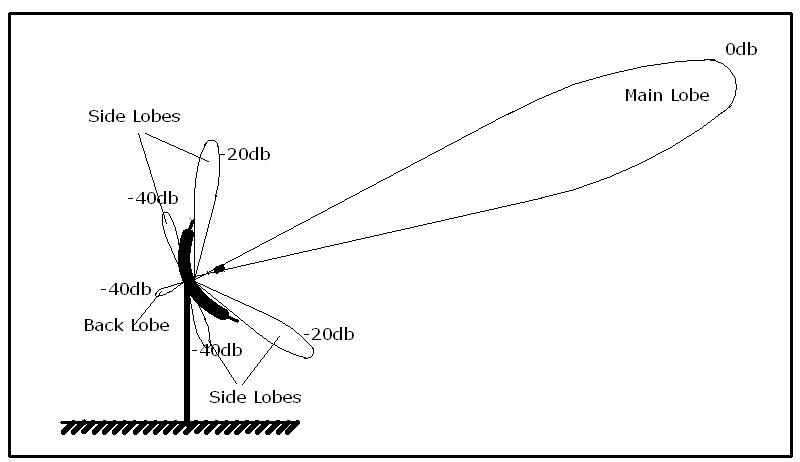
This is a simplified drawing of the dish radiation pattern We always think of a satelliste dish as a sort of searchlight looking for the sat signal, unlike a searchlight with its very narrow parallel beam the dish is wide angle in its viewing range, with side lobes front and rear which pick up signals from other satellites on the same frequency as we have selected for our viewing programme. Whilst these unwanted signals are not powerfull enough to provide an alternative picture they cause noise in our selected channel. When setting up in a low signal area the meter should be capable of reading signal strength and also signal quality and it is extremely important to adjust the dish not for best signal level but best signal to noise figure measured in decibels (db). It is vitally important to set the LNB to the correct offset figure given in the dishpointer programmes before starting these adjustments. If you only have a simple signal strength meter (hope its one with a pointer, not digital where the LEDs cannot be seen in strong sunlight) then with the help of someone in the caravan and the signal quality picture displayed on the TV, adjustment figures can be relayed to the dish. The best tool for this is a pair of walkie talkies which are also valuable for talking to the driver when backing the caravan into tree lined emplacements. Other caravanner will appreciate this rather than listenning to shouts of strong language. When in a very weak BBC/ITV area I find it is easier to set the system up on the strong signal of the SKY NEWS channel on Astra 2A Southern Europe Beam, Transponder 12207V, then do another adjustment on the weak BBC and ITV channels. If you are then unable to obtain a lock on the the BBC channel you know its not from poor adjustment, but too low a signal.
Plans for dish frame are now available in Charts page here
.....60 cm folded...........snow/sand cover.........motorised..........
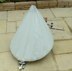
........step...................sloping ground............stormbars................